QUESTION
Is it possible to supply the PKU SR24 and PKUS SR24 from current substation circuit with a voltage of 110 volts?
Answer
Isolated PKU SR24 and PKUS SR24 could be supplied from the current circuit with voltage of 110 volts with their full operability and technical characteristics maintenance.
The operating voltage of all the digital inputs (the inputs of RPA and other commands) can also be set to 110 volts. Nevertheless, in the standard cabinets’ schemes, supplied by the plug of 220 volts, there are components (contactor, intermediate relays, alarm LEDs) for a voltage of 220 volts only. To ensure cabinets’ operation with PKU SR24 and PKUS SR24 the replacement with similar ones, rated for power from 110 volts is required.
If such a problem arises, contact us, and we will recommend the types of components that have the same overall dimensions and wiring diagrams (changes in the layout of the standard cabinet and its construction will not be required).
QUESTION
What types of SFP modules could be used in PKUS SR24?
Answer
In PKUS SR24 Control, Monitor and Connection Panel with System of Registration, various types of SFP modules can be used depending on the type of fibre-optic cable and its length.
The technical characteristics of SFP modules used in the PKUS SR24 are shown in the table below.

During the exploitation of MM-850mn SFP module for connection to standard IEEE C37.94 interfaces, an optical attenuator of 7..13 dB is installed at the output of its transmitter. In this case, with a sensitivity of the SFP module MM-850 mn less than -32 dBm at a speed of 2 Mbit/sec., the required budget of 9 dB is provided in compliance with the IEEE C37.94 standard, that allows using a multimode fibre-optic cable with a length of up to 2 km.
The SFP modules listed in the table above are used not only in the PKUS SR24, but also in the converters of the optical interfaces to the electrical E1 PKUS SR24 Module EO1 and PKUS SR24 Module EO2, as well as in the other equipment.
Generally, a multimode fibre-optic cable is laid inside the electrical substation, and the MM-850mn SFP modules are used. Although sometimes a single-mode FOC is installed inside the substation.
A single-mode fibre-optic cable of different types and lengths is installed between the substations, and here in PKUS SR24 a selection of suitable SFP module is required.
The type of supplied SFP module is determined during the equipment ordering.
QUESTION
What is the consumption of the cabinets with PKU SR24 and PKUS SR24? Which circuit-breaker should be installed on the power panel for these cabinets?
Answer
The average consumption for cabinets with PKU SR24 and PKUS SR24 does not exceed 100 Watts. Peak demand with synchronous response from all discrete inputs and outputs is not more than 200 Watts.
On the power supply panel for the cabinets with PKU SR24 and PKUS SR24, it is recommended to install a circuit-breaker with two Amperes rating and a K type characteristic for grading from the starting current.

By the use of circuit breakers with a rated current of two amperes with a different characteristic with a lower frequency, B type, for example, their activation with the panel power turn-on would be possible.
QUESTION
Is it possible to organize the TX/RX of commands between the Substation 1, where the PKUS SR24 + optical multiplexer is installed and the Substation 2, where the TX/RX is carried out not by the PKUS SR24, but by other equipment (Tebit, for example)? In other words, is it possible to have TX/RX of commands between objects, on one of which a PKUS SR24 is installed, and on the other, the other equipment for TX/RX of RPA commands, via optic?
Answer
The commands transmission between objects where, the PKUS SR24 is installed on the one side, and another Device for Transmission of Emergency and Control Signals (DTECS) is installed on the other side, is impossible.
The reason is that each DTECS via digital channels vendor uses its own closed exchange protocol, which provides the required time, reliability and safety of RPA commands’ signals transmission, as well as a number of other parameters. The use of the data of closed protocols by other external DTECS vendors without special permission is a copyright infringement.
That is why the DTECS of different vendors are incompatible between one and other at the data link layer. Even the same vendor, for some reason, could have no compatibility at data link layer between the different types of DTECS. For example, for the ABB Company a TEBIT, built-in to FOX515, and an NSD570 are incompatible at the data link layer.
For information, in 2011, our company proposed to FGC UES to carry out Research and Development, one of which tasks would be the development of a unified and recommended in Russia channel protocol of RPA commands signal transmission for all DTECS, both integrated into multiplexers and a remote, the owner of which would be FGC UES. Nevertheless, the project was rejected as insignificant, although the specialists of the PRA Service had fully supported the necessity of task solving.
QUESTION
Why your company's engineers do not load and refuse to load circuit-breakers, which are installed in cabinets of PKU SR24 and PKUS SR24 equipment?
Answer
Circuit-breakers installed in PKU SR24 and PKUS SR24 cabinets do not fulfil the functions of protection devices, and therefore do not provide selectivity. Data switching of circuit-breakers allows to remove control current from certain devices or circuits, which may be required during operation (for example, during localization of the short-circuit in the cabinet and checking of alarm system in the event of control current loss, etc.).
Inside PKU SR24 and PKUS SR24 cabinets there is no circuit-breaker, which could completely deenergize the entire cabinet, and which can provide the function of cabinet protection device.
Selectivity, as well as performance and sensitivity are to be provided by protection devices installed in the points of termination of conductors supplying power to the cabinet (generally it is a switchgear or power panel).
That fully complies with the requirements of paragraph 3.1.16 of the Electrical Installation Standard, Edition 7, which states:
“The protection devices must be installed directly at the protected conductors’ points of termination to the supply line. If necessary, it is permissible to take the length of the section between the supply line and the tap protection device up to 6 meters.”
In fact, the conductors’ length between power distribution panels and cabinets is often more than 6 meters. Therefore, it is not possible to install protection devices in PKU SR24 and PKUS SR24 cabinets only, because, in most cases, according to the Electrical Installation Standard the protection device is required on the power distribution panel. That is why Unitel Engineering LLC does not install protection devices inside the PKU SR24 and PKUS SR24 cabinets.
That is the reason why the engineers of our Company do not load circuit-breakers, installed in PKU SR24 and PKUS SR24 cabinets, but only check their switching capacity.
QUESTION
On the four substations (S1 to S4) there is a SDH transport network, to which access multiplexers are connected. Could the following structure of commands transmission be realized with the help of PKUS SR24: Commands 1-8 are transmitted and received between S1-S2, S1-S3 and S1-S4. Commands 9-24 are transmitted and received between S1-S2, S1-S3.
Answer
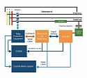
That structure of RPA commands’ signals transmission is possible. PKUS SR24 allows transmitting of commands’ signals to several directions, if the multiplexers have the possibility of cross-commutation level on 64 kilobytes per second. In addition, in PKUS SR24 the mechanisms for T-schemes organization with the logic ‘AND’ and ‘OR’ are implemented The use of these mechanisms makes it possible to realize structure of the RPA commands’ signals transmission specified in the question, which is shown in the picture below.

In PKUS SR24 on S1 the commands’ inputs and outputs are distributed between two logical directions TPE1 and TPE2, for which separate time-slots from first to sixth are allocated in the E1 stream: TPE1 1-8, TPE1 9-16, TPE1 17-24, TPE2 1-8, TPE2 9-16 и TPE2 17-24 (see the picture below). Moreover, the commands’ outputs respond regardless of which direction the command came from (the logic ‘OR’ is applied). In the access multiplexer the time-slots from the E1 stream are allocated to two VC12 containers, one of which with TPE1 time-slots is transmitted to the S2 and the other with TPE2 time-slots to the S3.
On S2 in PKUS SR24 the inputs and outputs of commands 9-24 are entered on time-slots 2 and 3 (ТPE2 9-16 and TPE2 17-24). The received commands from the first time-slot TPE2 1-8 are directed to the outputs of commands 1-8 and simultaneously to the fourth time-slot TPE1 1-8. The received commands from the fourth time-slot TPE1 1-8 are redirected to the first time-slot TPE2 1-8 simultaneously with the commands from the inputs of commands 1-8 (the logic ‘OR’ is applied). In other words, commands 1-8 will be transmitted to the S1 direction regardless of whether they come from the inputs of PKUS SR24 to the S2 or were received at the PKUS SR24 in the fourth time-slot TPE1 1-8. In the access multiplexer, the time-slots from the E1 stream are allocated to two VC12 containers, one of which is transmitted to the S1 with three time-slots TPE2 and the other to the S4 with one time-slot TPE1.
Processing similar to S2 processing is performed in the PKUS SR24 and the S3 access multiplexer.
At the PKUS SR24 on the S4, the received commands from the first and second time-slots TPE2 1-8 and TPE1 1-8 are output simultaneously through the ‘OR’ logic to the outputs 1-8. The received commands from the second time-slot TPE1 1-8 are redirected to the first time-slot TPE2 1-8 simultaneously with the commands from the inputs of the commands 1-8 (the logic ‘OR’ is applied). The same is realized in the direction from the first to the second time-slot. In the access multiplexer the time slots from the E1 stream are allocated to two VC12 containers, one of which is transmitted to the S2 with time-slot TPE2 1-8 and the other to the S4 with time-slot TPE1.

That processing allows simultaneous transmission and reception of 1-8 commands between the S1 and the S4 through the S2 and the S3. If a failure occurs in one direction, for example, power-off at the access multiplexer at the S2, then commands 1-8 will be transmitted between the S1 and the S4 through the S3.
Moreover, the use of the ‘OR’ logic allows to organize the structures when, for example, the command 1, formed on any of the Substations, will be simultaneously received on all other Substations, and commands 2-24 will be transmitted in accordance with the structure described above. The number of Substations, from and to which commands 1-8 are sent, could be also increased.
As the time-slots allocation in the PKUS SR24 is completely flexible, it is possible to implement the specified commands transmission scheme without changing the time-slots numbers in the Digital Data Transmission System (DDTS) in E1 streams, as shown below (unused time-slots are not indicated at the picture).
To reserve channels in the DDTS using the main and backup routes, it is necessary to use the TPE1* and TPE2* reservation mechanism built into the PKUS SR24 (TPEx and TPEx* transmit the same information about the commands). Аn example of implementing a reservation with the change of the time-slots numbers in the DDTS in E1 streams is provided below.

However, the time-slots selected for the main directions of TPE1 and TPE2 are routed through the DDTS by the main shortest routes, and the time-slots assigned to the reserve directions TPE1* and TPE2* are routed through the reserve routes available in the DDTS, as shown in the pictures below.


PKUS SR24 receiver simultaneously analyzes as the main and as the backup routes, and if, for example, the main route disappears, then a switch to the backup route will occur without a time delay. Thus, if the loss of one of the routes occurs during the command signal transmission, its reception will be uninterrupted.
QUESTION
Is it possible to deliver relay modules without keys into PKU SR24 and PKUS SR24? If yes, what is required?
Answer
The delivery of relay modules without keys is possible both to PKU SR24 and to PKUS SR24.
The delivery of both PKU SR24 and PKUS SR24 is carried out according to the questionnaire for preparation of the proposal for equipment of PKU SR24 and PKUS SR24. In this questionnaire for order, it is necessary to specify which relay modules should be delivered with keys and which without keys.
The example of order of PKU SR24/16 or PKUS SR 24/16 (the number of processed commands is 16), where the first four relay modules are without keys and others with keys.

QUESTION
We have PKU SR24 panel installed. Can it be modified to PKUS SR24, and if it is possible, what should be done in order to transmit the RPA commands via digital networks or dedicated optical fiber?
Answer
PKUS SR24 is developed based on PKU SR24 panel. Thus, the modification of PKU SR24 to PKUS SR24 is possible.
Two options of such modification are possible.
First option is the complete replacement of control unit at the facility. The advantage of this option is the minimum amount of installation work at the facility and complete testing of the control unit at the Unitel Engineering manufacturing plant. The disadvantage is the possibility of control unit damage during transportation.
Second option is a replacement of processor module, replacement of the front and back panels of the control unit, installation of the communication module and, depending on necessity, the electrical interface module or the optical interface module. The advantage of this option is the maximum use of previously installed modules and a lesser probability of modules damage transportation (in the relevant packaging). Disadvantage is a large amount of installation work on the facility with the possibility of the installed modules damage, for example, from electrostatic discharges with poor grounding.
As the PKU SR24 is installed in the cabinets, depending on the implemented cabinet layout and the required according to the design decision cabinet layout, the PKU SR24 may require the replacement of some elements, for example, the output of received commands common key and the installation of a small amount of additional signal cables.
QUESTION
What is the difference between PKU SR24 produced by Unitel Engineering and the panel SR24 produced by ABB company?
Answer
Despite the appearance similarity and similar functionality there are many differences between two devices.
In PKU SR24 circuit and software solutions different from SR24 are used. PKU SR24 implements all functionality of SR24 of ABB Company and, moreover, has a number of main differences:
· Circuit and software solutions, which provide PKU SR24 the requirements for electromagnetic compatibility in accordance with the forth and special impacts by A criteria and increase the device's security against false activations, failures and hang-ups under the influence of powerful impulse noises;
· Discrete inputs’ of PKU SR24 parameters compliance with the latest standards and additional requirements of FGC UES, for example, STO 56947007-33.040.20.123-2012 “Release specifications for automatic protective devices”: the operation thresholds for discrete inputs of relay modules 160 ... 170 volts, remaining current input - 20 mA, the setting of the delay for triggering - 0 ... 20 ms;
· Duplicating (backup) circuits of discrete inputs on relay modules in transmission direction;
· The ability to generate IRIG-B synchronization signals from the internal clocks of PKU SR24 for external devices, which allows to synchronize the time stamps of various devices event recorders at facilities where there are no GPS / GLONASS synchronizers;
· Special mode for commands processing the ‘retransmission’, which, if necessary, blocks the output of the signaling about the passage of certain RPA commands (they are selected during the configuration in HMIPanel program) to the substations’ central alarm system;
· Special mode of PKU SR24 for the formation of long commands for the Device for Transmission of Emergency and Control Signals (DTECS), which are not possible to transmit such commands;
· Absence of excessive emergency signaling of PKU SR24 at control amplitudes on the discrete inputs of the relay modules outside the guaranteed operation zone;
· Absence of overflow and subsequent data loss of PKU SR24 event recorder during the relay modules failures;
· Graphical regained mode for occurring events, alarms and facts of receiving and transmitting command signals (an oscilloscope) in the HMIPanel user interface program;
· Seven producers of automatic process control system, in which integration is performed;
· Possibility of relay modules SKO without keys ordering;
· Support for saving of events read out from the recorder in COMTRADE format.
· The possibility of modification, if necessary, of installed and operated PKU SR24 to PKUS SR24, additional information is given here.
SR24 of ABB company could be replaced by the SR24 by Unitel Engineering almost without project documentation changing in any project (only the name of equipment and the name of equipment manufacturer is required to be changed). Reverse replacement is not always possible.
QUESTION
Why is it necessary to use the IEEE C37.94/E1 converters of PKUS SR24 EO1 or PKUS SR24 EO2, if a number of manufacturers offer integrated to access multiplexers modules with IEEE C37.94 interfaces? It is easier to use the IEEE C37.94 interfaces integrated into the access multiplexers, whose operation will be controlled from the network management systems, in the construction of communication networks, isn’t it?
Answer
Yes, the operation of the IEEE C37.94 interfaces integrated to the access multiplexers can be controlled from the network management systems that are managed by the Supervisory Control System services. However, this is the only advantage, and the refusal to use the IEEE C37.94 interfaces integrated to the multiplexers has a number of objective reasons.
As the integrated IEEE C37.94 interfaces are usually developed by the developers of telecommunications equipment for telecom operators, they fully or partially have the following disadvantages:
1. The IEEE C37.94 interface modules integrated to the access multiplexers do not provide monitoring of status of the channels used for RPA equipment operation. They do not have any ‘dry’ emergency contacts for outputting information about the channels status for RPA, neither in the central alarm system of the substations, nor in the Automatic Process Control System of the facilities. It is also not possible to output this information to the Automatic Process Control System using standard protocols, for example, IEC 60870-5-101 or IEC 60870-5-104. Information on the status of the channels for RPA is available only in control network systems of Supervisory Control System services, which are not connected with the central alarm systems of substations and Automatic Process Control Systems.
2. In these modules, there are no non-editable, non-volatile event recorders. All events related to channel failures for RPA can be eliminated either by turning off the power supply or by using control systems. System logs are stored in management systems in files that are accessible for editing and unwanted events can be deleted from them. This can significantly complicate the identification of the technological violations cause during investigations.
In PKUS SR24 EO1 and PKUS SR24 EO2 (hereinafter PKUS SR24 EOx), in order to eliminate the above disadvantages of the IEEE C37.94 interface modules integrated in the access multiplexers, it is provided:
· ‘Dry’ contacts for signaling accidents, both the equipment itself and communication channel failures;
· Integration to the Automatic Process Control Systems via RS-485 interface according to IEC 60870-5-101 (according to IEC 60870-5-104 using RS485/Ethernet converter);
· Nonvolatile event recorder without editing capability;
· Event log data saving using application software in files with non-editable format;
· The ability of timestamps synchronization in the event recorder using IRIG-B signals. Moreover, the use of PKUS SR24 EOx allows more flexible organization of channels with IEEE C37.94 interfaces.
· Channels with IEEE C37.94 interfaces are organized by a ‘point-to-point’ scheme, as shown in the picture below. For their organization, access multiplexers and IEEE C37.94 interfaces of the same vendor are used.

The IEEE C37.94 installed into access multiplexers interface modules only support the internal bus of this multiplexer and could not be installed into others. If the multiplexers from different vendors are used to organize a channel with IEEE C37.94 interfaces, such solutions will be inefficient, as shown in the following picture

If multiplexers of access of different vendors are used at different substations, the organization of RPA channel with IEEE C37.94 interfaces will be possible with the use of PKUS SR24 EOx, which is shown in the picture below. E1 interfaces are widely distributed in multiplexers of different vendors and are compatible with each other.

In a case of a transport network STM-4 or higher, it could be possible to refuse to use the access multiplexers to RPA channels organization with E1 interfaces, for example, as shown in the two pictures below. Transport multiplexers could be from different vendors. The transport multiplexers by themselves do not have modules with IEEE C37.94. interfaces in their composition.


Thus, the use of the PKUS SR24 EOx instead of the modules with IEEE C37.94 interfaces integrated into allows:
· To eliminate the disadvantages inherent to IEEE C37.94 interfaces integrated into access multiplexers;
· To eliminate the dependence from a single multiplexing equipment vendor in the expansion of Digital Data Transmission System and the organization of channels with IEEE C37.94 interfaces for Relay Protection and Automation (resolving the market monopolization issue);
· To implement channels with IEEE C37.94 interfaces for Relay Protection and Automation more flexible, in some cases excluding the use of access multiplexers, which reduces the cost of channels realization, simplifies the Digital Data Transmission System topology, increases the reliability of channels for RPA equipment and reduces the costs of their operation.
QUESTION
Answer
Yes, such connection is possible.
To achieve that, the IEEE C37.94 interface must be present in the Lines’ Differential Protection (LDP) terminal, and the free electrical E1 interface should be available as a part of the Digital Data Transmission System (DDTS) multiplexer.
The picture below shows an example of a channel organization for LDP between S1 and S2 with a use of electrical interface converters to an optical PKUS SR24 EO1 or PKUS SR24 EO2 (hereinafter PKUS SR24 EOx) and DDTS multiplexers.
 (1).jpg")
In the program settings of the IEEE C37.94 interface of PKUS SR24 EOx, it is necessary to set that data transfer speed (to set the number of used time-slots at 64 kbit/sec.) with which the LDP terminals operate. The data transfer speed via DDTS between the used E1 interfaces should be no less than established in the LDP terminals and in the PKUS SR24 EOx (high speed is permissible).
Moreover, certain requirements are imposed on the DDTS itself: it is necessary to know the delay of data transmission in the network between the used E1 interfaces and its asymmetry in the directions of reception and transmission.
Due to the LDP vendors the permissible delay value is up to 30 ms, the asymmetry should not exceed 100...300 mcs (the differential current caused by asymmetry should not exceed 2...5%). If the channels asymmetry in the DDTS exceeds the specified values, synchronization of the LDP terminals by time, for example, with a use of GPS/GLONASS synchronizers, is necessary to prevent false protection operation.
First of all, the delay and asymmetry of the channels in the DDTS depends on its construction technology and the type of equipment used.
QUESTION
Answer
Such organization of commands signal transmission is possible.
In the control, transmission and communication with PKUS SR24 registration system panel, the commands are divided into three groups: 1-8, 9-16 and 17-24. Each group is transmitted in its digital stream (in its own time slots). Moreover, for each group, two logical directions for receiving and transmitting TPE1 and TPE2 are provided, for which their digital streams are also allocated. Thus, it is possible to send and receive commands in six directions maximum.
An example is shown at the picture below. Here, the commands 1-7, 8 and 9-10 are transmitted and received in three directions: the commands 1-7 between the S1 and the S2, the command 8 between the S1 and the S3 and the commands 9-10 between the S1 and the S4.

In UMUX1500 multiplexer the time-slots from E1 stream transferred to the LOMIF module from PKUS SR24 are distributed in the SYNAC module to three VC12 containers that are transmitted via transport network to three Substations. Below is an example where the commands of each group are transmitted in the E1 stream at 64 kbit/sec. (one time-slot is used for each group). The using of a larger number of time-slots for each group will result in a shorter time for the RPA commands transmission.

The connection of the control, transmission and communication with PKUS SR24 registration system panel can be made directly to the multiplexers via the E1 electrical interface with a use of twisted pair. However, due to the presence of electromagnetic interference and the presence of potential between the installation locations of the multiplexer and PKUS SR24 at the Substation, it is recommended to use a fibre-optic cable (FOC) in case of short circuits on the transmission line.
To achieve that, converters of optical interfaces to electrical E1 are used, these are single-channel PKUS SR24 EO1 or four-channel PKUS SR24 EO2 (hereinafter PKUS SR24 EOx), which are installed in cabinets with multiplexing equipment or next to them. The type of the optical interfaces PKUS SR24 and PKUS SR24 EOx in this case is preferable to install programmatically as an optical E1 (linear code CMI, cycle format G.704).
There could be any type of FOC, both multimode 850 nm and single-mode 1310 nm or 1550 nm, because PKUS SR24 and PKUS SR24 EOx use SFP modules, which can be selected based on the type of FOC used.
If the reservation of channels in the transport network with a use of the main and backup routes is required, you need to use the TPE1* and TPE2* reservation mechanism built into the PKUS SR24, for which separate digital streams are used, and for S2, S3 and S4 to install PKUS SR24 EO2 converter in the multiplexing mode of two electrical interfaces E1 into one optical interface. In the transport network, the main and reserve E1 streams are organized.
The main and backup routes for the channel between the S1 and the S2 are shown at the picture below. For the channels between S1 and S3 and between S1 and S4, the main and backup routes are organized in a similar manner.

During the commands transmission in three directions with reservation of routes in the UMUX1500 multiplexer, the time-slots from the E1 stream transferred to the LOMIF module from PKUS are distributed in the SYNAC module to six VC12 containers, three of which form to the main routes in the transport network, and three to reserve ones. Below is an example where the commands of each group, both in the main and in the backup directions, are transmitted in the stream at 64 kbit/sec. (one time-slot is used for each group).

The disadvantage of such solutions is the incomplete workload of E1 streams transmitted from S1 to S2, S3 and S4.
The main advantage of the solution is elimination of UMUX1500 access multiplexers from the network on S2, S3 and S4, which allows:
· To reduce the cost of implementation of the solution connected with RPA commands transmission;
· To simplify the network topology, which increases the reliability of organized channels of RPA commands transmission, and to reduce the cost of its operation;
To reduce the probability of staff errors connected with the channels for RPA commands transmission, with reconfiguration of the network for any purpose (addition of telemechanic channels, telephone channels, etc.), because in the used E1 streams (VC12 containers), it is impossible to transfer any other information.